Receive APT with HackRF
How to receive APT information from NOAA Satellites using an HackRF.
This was an University Project that I did with my colleague Ricardo Boinho during our Electrical and Computer Engineering Course, for the classes of "Radiation and Propagation of Electromagnetic Waves" and "Telecommunications Systems I".
The goal of this project was to receive a full image from a passing weather satellite (NOAA constellation), using a software defined radio and homemade antenna.
This article is a summary of the actual project, hope you enjoy.
NOAA Satellites
NOAA (National Oceanic and Atmospheric Administration) started the satellite program back in 1978, and have been updating the constellation ever since, it uses two satellites, a morning and afternoon satellite, to ensure every part of the Earth is observed at least twice every 12 hours.
Severe weather is monitored and reported to the National Weather Service which broadcasts the findings to the global community. With the early warning, effects of catastrophic weather events can be minimized.
NOAA owns 9 satellites, which includes: 4 geostationary (GOES-14, -15, -16 and -17), 4 polar-orbiting (NOAA-15, -18, -19 and -20), and the DSCOVR. NOAA operates, but does not own, 7 satellites, which includes: Suomi NPP, Jason-3, 4 DMSP satellites, and the EWS-G1 satellite.
Source: Currently Flying | NOAA - NESDIS
The interesting fact about these satellites is that not only they capture the images but they broadcast it directly down to Earth when they are passing by, in fixed frequencies and with open communications (not encrypted).
These weather satellites in polar orbits, called Polar Operational Environmental Satellites (POES) have three downlink systems, Automatic Picture Transmission (APT), High Resolution Picture Transmission (HRPT) and Direct Sounder Broadcasts (DSB).
The main difference between APT and HRPT is that APT is a VHF signal and HRPT is a UHF signal, for this reason the HRPT service sends a lot more data (higher resolution images and instrument information).
Since to receive HRPT we need a large satellite dish which we don't have, we decided to focus on APT.
The APT system was developed for the continuous transmission of low quality images of the earth's surface, with low-cost terrestrial receivers. The ground station consists of a directional antenna capable of tracking the satellite or a fixed omnidirectional antenna, a VHF (Very High Frequency) receiver and a display device. The signal transmission band is between 137 and 138 MHz. It is a narrow band, close to the band allocated to commercial flights, in which the transmission of these signals by satellites is done by frequency modulation (FM), with a modulated carrier in amplitude (AM).
The bandwidth of the receivers is made by using a filter in the intermediate frequencies (IF), which cannot be too narrow or too wide, otherwise it causes distortion or introduces a lot of noise, respectively. For this, two factors must be taken into account, the deviation of the carrier during transmission (+/- 17 KHz) and the Doppler effect (+/- 4.5 KHz). The recommendation for the filter bandwidth is 40 KHz (+/- 20 KHz).
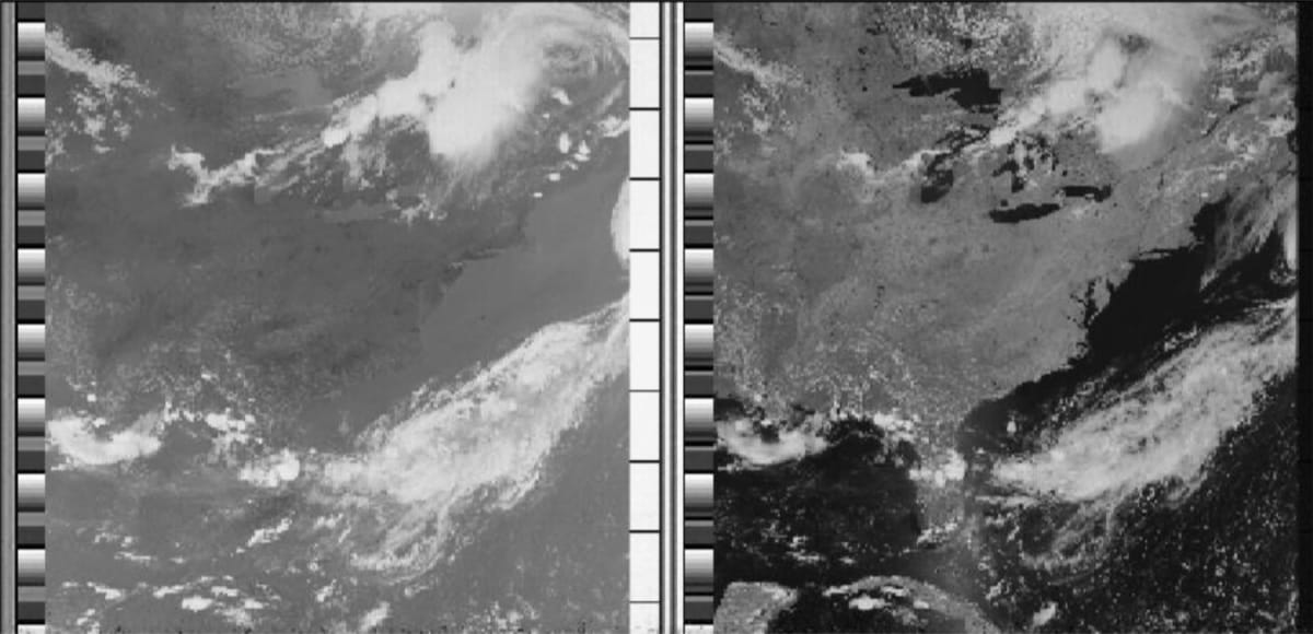
The latter causes a shift in frequency as the satellite passes through the ground station. Due to the low signal strength (Transmission power = 5 W) it is recommended to use preamps with low noise, that is, high gain and low noise figure. Recommended values are 1 dB for the noise figure(the noise figure should be as low as possible) and 15 to 20 dB for the gain. The APT signal is derived from the original information (used for the HRPT signal), in which only two channels of the original are transmitted, and this is achieved through multiplexing. The signal scan rate is 120 lines per minute. Therefore, it sends 2 images, depending on whether the satellite passes during the day or night. During the day, one of the images is from the visible channel and the other from the infrared channel (image below). At night, the two images are from the infrared channel in different spectral bands.
| Satellite | Service | Frequency | Launch Year |
|---|---|---|---|
| NOAA 15 | APT | 137.62 MHz | 1998 |
| NOAA 18 | APT | 137.9125 MHz | 2005 |
| NOAA 19 | APT | 137.10 MHz | 2009 |
Antenna
One of the most important factors when receiving a signal is the antenna.
Therefore, you have to consider 3 main conditions: the physical size, polarization and gain of the antenna. The physical size is affected by the frequency of the received signal (f), that is, it is related to the wavelength (λ), since λ = propagation speed / frequency.
The polarization of the antenna must match the polarization of the received signal, to maximize its average power density.
The antenna gain must be high enough to be able to recover a signal, in this case where we want to receive the APT signal, antennas for VHF (Very High Frequency 30 – 300 MHz) must be considered. For this use case, we can consider omnidirectional or directional antennas.
Omnidirectional antennas have the advantage of not needing a satellite tracking and tracing system. In the case of crossed dipoles (directional antennas), the gain they offer is very small, so the signal to receive may not be recovered and, due to the positioning of its elements, the signal capture is better in one direction than in others. This can cause some loss in signal strength, causing the APT signal image to fail. In helical four-wire antennas there is no loss of signal strength as in cross-dipole antennas and they have a better radiation diagram than the latter. Its radiation diagram is omnidirectional in the plane perpendicular to the main axis and has an almost circular polarization seen in the vertical plane. They are considered nearly perfect for receiving signals from meteorological satellites in polar orbits. Its gains are between 3 and 5 dB. When the satellite reaches an elevation above 10 degrees from the horizon, signal reception is practically noise free. In directional antennas you get a higher gain, and in turn a better signal-to-noise ratio, compared to omnidirectional ones. This is because their radiation diagram presents a great gain in a certain direction (main lobe) and a low gain in other directions. Thus, in these cases, a satellite tracking and tracing system is needed so that the direction of greatest gain is always aligned with the satellite. Yagi cross antennas are good for receiving APT signals, low cost and easy to build. They are called criss-crosses because the adjacent elements are 90 degrees apart.
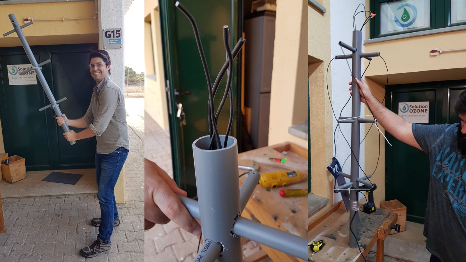
Building the Antenna
For the previously described reasons we decided to use and build a Quadrifilar Helix(QHF) Antenna for this project.
We referred to this Instructables Tutorial to build the antenna (I will be skipping most of the build details as they are very well detailed in this tutorial).
The materials used were:
- PVC pipes
- 2.5mm copper wire pool
For the APT signal frequency of 137.5 MHz, the wavelength is approximately equal to 2,1818 meters. We searched for an online calculator for Quadrifilar Helicoidal Antennas and we found one: Jcoppens - Quadrifilar Helicoidal Antenna Calculator and it's also referred in the Instructables Tutorial previously mentioned. In this online calculator, we used the following inputs:
- Operating frequency: 137.5 MHz;
- Number of laps: 0.5 laps;
- Length of a revolution: λ;
- radius of curvature: 15 mm;
- Conductor diameter: 7 mm;
- Diameter/height ratio: 0.44;
From this online calculator we obtained the physical parameters of the antenna, including the small loop and the large loop. Each loop is formed by two half-curve helical conductors, the smaller two corresponding to the small loop and the larger two to the large loop.
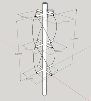
The result:
Receiving Data
The materials used to received data were:
- HackRF One
- The antenna we built above
- LNA (SPF5189Z)
- 75 ohm antenna cable
HackRF ONE
HackRF One is a SDR (Software Defined Radio) peripheral capable of transmitting or receiving radio signals from 1 MHz to 6 GHz, it was designed to allow the testing and development of modern and next generation radio technologies. HackRF One is an open source hardware platform that can be used as a USB peripheral or programmed for standalone operation. HackRF One works like a computer sound card. It processes digital signals to radio waveforms, enabling the integration of large-scale communication networks.
Technical features:
- 1 MHz to 6 GHz operating frequency
- half-duplex transceiver
- up to 20 million samples per second
- 8-bit quadrature samples (8-bit I and 8-bit Q)
- compatible with GNU Radio, SDR#, and more
- software-configurable RX and TX gain and baseband filter
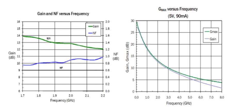
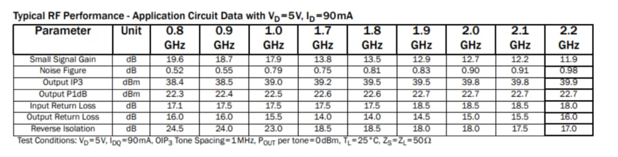
LNA - Low Noise Amplifier
The LNA we used was the SPF5189Z amplifier, designed to operate between 50Mhz and 4000Mhz, this was chosen because the SPF5189Z offers an extremely low noise value and high linearity in a block gain configuration. One of the parameters analyzed for choosing this LNA was its signal gain / noise figure / signal frequency ratio, and the fact that its maximum gain occurs at low frequencies. Maximum variation of the Noise Figure: 0.6 dB (between 50Mhz and 4000Mhz)
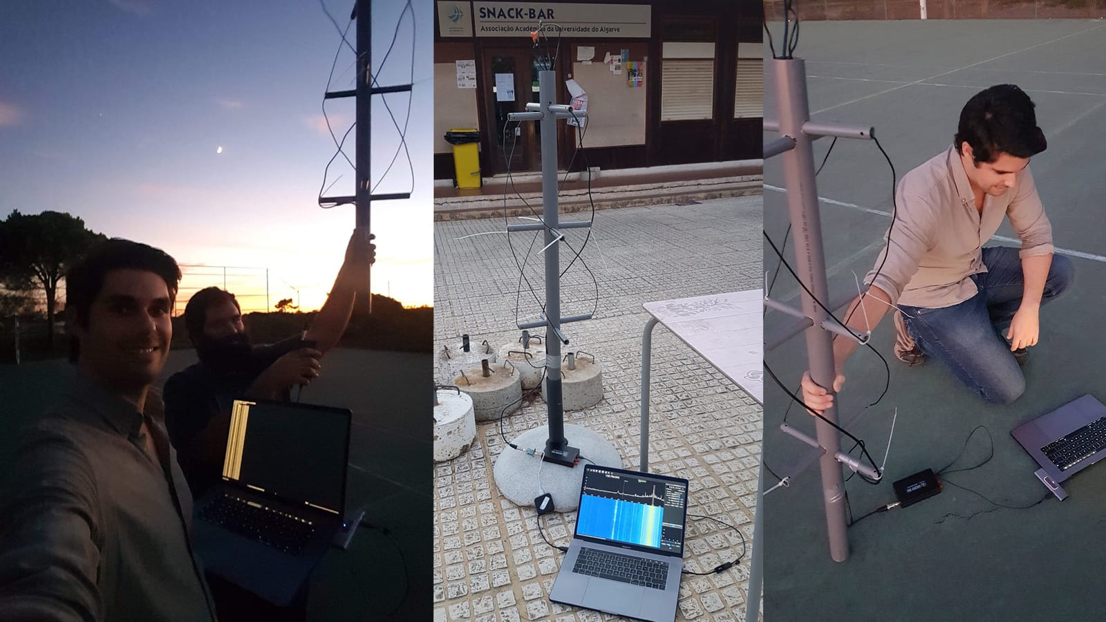
We connected the antenna to the LNA and the LNA to the HackRF One using the coaxial cable, controlling and observing through the computer using an open source software called GQRX, which is developed on top of the GNU Radio and QT software, also open source.
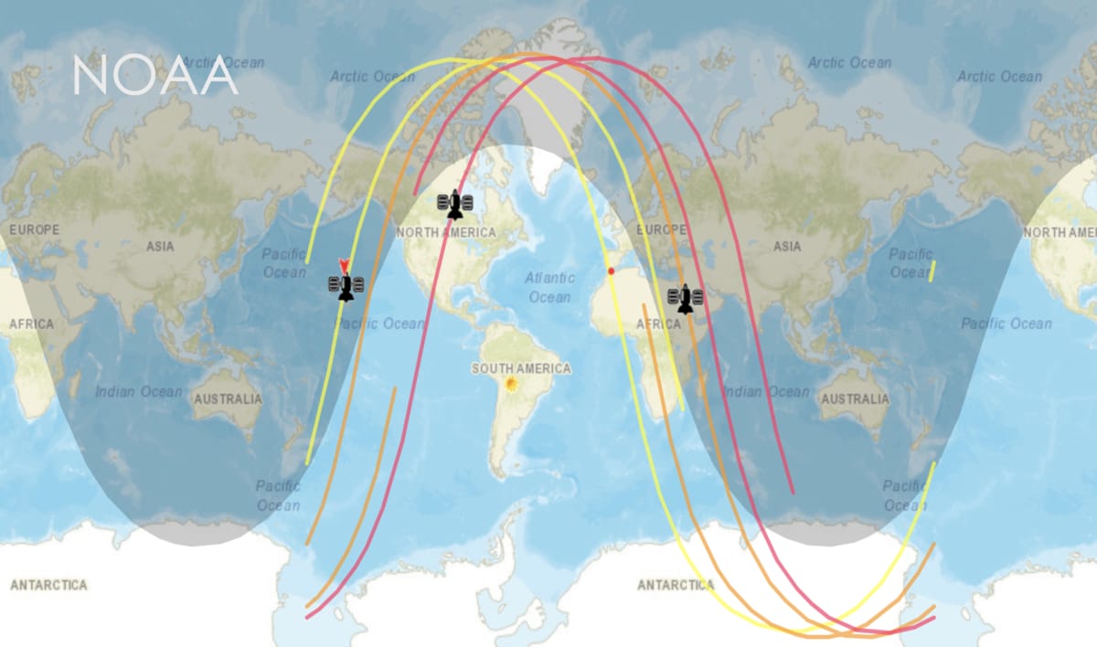
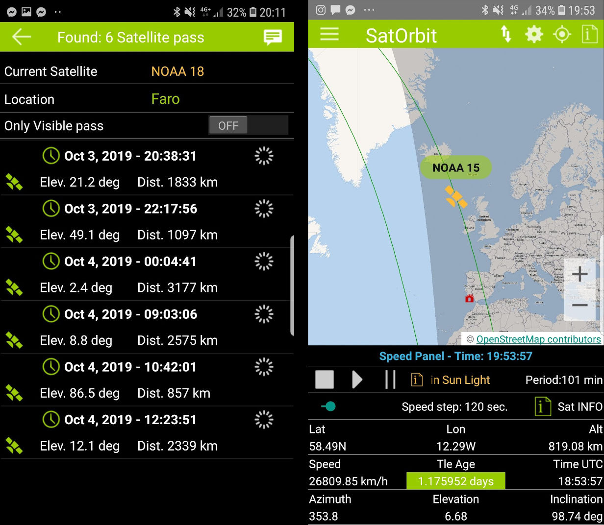
We also used a free android application (SatOrbit) was used to track the satellites in order to know when they passed over Portugal, also knowing their height and inclination.
Before the readings, a check was always made to test whether the radio was capturing and decoding signals in the various frequencies (e.g. commercial FM radio stations), also positioning the horizontal plane of the antenna as a function of the satellite's inclination to optimize the results. On the computer, using the GQRX software, the central frequency was set at 137.5 MHz with a bandwidth of 40 KHz, as recommended.
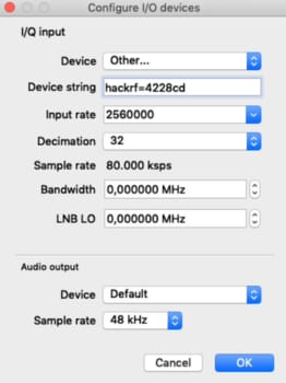
As the total bandwidth required is about 40 KHz, we can increase the sampling rate in order to increase the resolution of the ADC. Therefore, with a 32x decimation of the Nyquish sampling frequency (sample_frequency = 2 * 40 KHz), it is possible to increase the resolution of the ADC, thus also filtering part of the noise due to the low-pass filter used for decimation. Doing this allows us to improve the signal to noise ratio in the output.
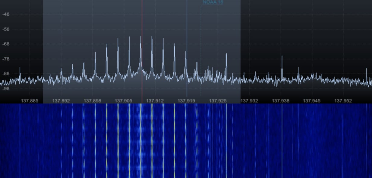
The signal we were looking for and never received:
In Conclusion
Although we did many reading attempts, it was not possible to obtain the APT signal. There are several factors that can contribute to this failure, such as geographic location of the reading (interferences), lack of expertise in the control of the HackRF One software GQRX, small symmetry errors in the construction of the antenna.
We can't also rule out satellite malfunction as it has happened frequently in the past(Weather Satellite NOAA 15 Appears to have Failed (Again)) and the APT signals are not a priority for the these satellites as the scientific data that matters to the organization is broadcasted through HRPT.
The geographic locations where the readings were taken, were in the city of Faro and Montenegro. The problem with these locations is interference, as first there is an airport near the city (500m to 2kmin distance to where there readings were taken), then as it is a city there seems to be some extra interference (many signals), plus there seems to be a lot of amateur radios in this area that can be operating near or even on the signal frequency, which makes reception unfeasible.
This proximity to the airport concerned us specially due to the proximity between the commercial flights band and the APT signal frequency since we are near the airport.
Although during the various readings we acquired expertise in them and we constantly double checked the parameters recommended by others in similar projects, we cannot rule out this possibility of error, as we still have to improve our skills using GQRX.
During assembly of the antenna, due to human error, the markings of the horizontal dividers on the main structure were not exactly at 90 degrees, as this can influence the efficiency of the antenna capturing the APT signal, but we don't believe this can be the main issue.
Over our several attempts to capture the APT signal, we kept receiving other signals such as a music signal, which was eventually identified as a replica of commercial radios operating within the 87.5 - 108 Mhz spectrum. In other readings, a digital signal was detected, which we assume Faro Airport to be the source of the signal, due to the fact that it becomes stronger when we move towards the airport.
In the future we would like to retry the experiment on some hills far from the airport and the city.